
1. Introduction
LEO constellations are transforming satellite communications. With networks like Starlink, OneWeb, and Amazon Kuiper already in orbit and dozens of new programmes in development, the engineering challenge has shifted from launching to maintaining timing integrity at constellation scale. LEO satellites travel at up to 7.5 km/s, requiring seamless multi-satellite handovers, aggressive Doppler compensation, and nanosecond-level synchronisation across a distributed mesh network.
Frequency control components sit at the foundation of this challenge. Timing errors introduced at the oscillator level cannot be corrected downstream — phase noise, jitter, and frequency instability propagate through every stage of the signal chain, corrupting data, degrading SNR, and destabilising beamforming arrays. Specifying the right component at each node is not an optimisation exercise; it is a system integrity requirement.
TechPoint Golledge provides a single-source portfolio spanning every frequency control requirement in the LEO signal chain — from ultra-low jitter SPXOs for baseband clocking, to –180 dBc/Hz OCXOs for satellite payload master references, to AS9100-certified supply chain support for mission qualification.
2. LEO Signal Chain Architecture — TechPoint Golledge Product Mapping
Figure 1 maps the complete LEO communications signal chain end-to-end, identifying the functional block at each node, the recommended TechPoint Golledge product category and model, and the consequence of incorrect component selection. Three physical domains are shown — Ground Segment Uplink, Space Segment Payload, and Ground Segment Downlink — plus system-wide timing hierarchy and failure propagation chain.
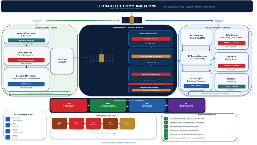 Figure 1: LEO Constellation Timing Signal Chain — TechPoint Golledge Product Mapping (AN-LEO-001)
3. Where Current LEO Designs Fall Short
The LEO opportunity is attracting engineering talent from telecoms, defence, and automotive — and with it, a set of inherited assumptions that do not transfer cleanly to satellite signal chains. Four patterns are quietly degrading constellation programmes:
• Oscillators selected late in the design cycle — treated as a late-stage procurement decision rather than a foundational architectural choice. By the time the impact of phase noise on system SNR is modelled, PCB layout is locked and component options are constrained.
• DSP assumed to correct timing errors — it cannot. Phase noise introduced at the source oscillator is not recoverable in software. This is a mathematical constraint, not an implementation gap. Engineers from DSP-heavy terrestrial backgrounds often underestimate this until it manifests as unrecoverable BER degradation.
• Phase noise treated as a datasheet number, not a system constraint — its significance emerges only when integrated across bandwidth, mapped through each conversion stage, and modelled against ADC aperture. Too few teams perform this end-to-end analysis before component selection.
• Timing and beamforming treated as separate engineering domains — AESA payloads require absolute phase coherence across hundreds of antenna elements. Disconnecting the timing architecture conversation from the RF team is a structural programme risk with direct impact on link quality.
These are not edge-case failures. They are patterns appearing repeatedly across new entrant programmes — and they are entirely avoidable with the right architecture decisions made early.
4. Node-by-Node Product Selection & Risk Analysis
The table below provides the complete product selection reference mapped to each signal chain node, including key model references, critical specifications, and — critically — the engineering risk if the wrong part is specified.
Signal Chain Node | Product Category | Key Models | Critical Specification | Risk if Wrong Part |
Baseband / DSP (Uplink & Downlink) | Clock Oscillators (SPXOs) | GXO-3306 Series | -153 dBc/Hz 0.04 ps RMS jitter | ADC SNR collapse BER degradation |
Up-Converter PLL Synthesiser | VCXOs | GVXO Series (to 2.1 GHz) | ±250 ppm pulling ±25 ppm stability | PLL unlock during Doppler shift |
Portable Terminals & CubeSats | TCXOs / VCTCXOs | GTXO Series (to 1.5 GHz) | ±0.05 ppm stability 1.6×1.2 mm footprint | Freq instability over temp → link loss |
Satellite Payload Master Clock (PLL Ref) | OCXOs | GOXO-430 / 431 | -180 dBc/Hz 1 ppb stability | Beamforming drift Link instability |
IF Filtering (Payload & Ground) | Crystal Filters & SAW Filters | GSF / GSW Series (to 3.7 GHz) | 2 kHz BW 2 dB insertion loss | Image rejection fails Spurious interference |
GNSS / NTP / Holdover | OCXOs + RTC Modules | GOXO Stratum 3E + RV-3xxx | Stratum 3/3E Ultra-low aging | Holdover drift Handover failure |
5. Design Considerations
5.1 Phase Noise Is a System Constraint, Not a Datasheet Number
A phase noise figure of –153 dBc/Hz or –180 dBc/Hz has limited meaning in isolation. Its significance emerges when integrated across the system bandwidth, mapped through each conversion stage, and modelled against ADC aperture jitter. Engineers should perform end-to-end noise budget analysis before finalising oscillator selection, not treat phase noise as a pass/fail threshold.
5.2 The OCXO Is the Master Reference — Not the VCXO
A common architectural error in LEO payload design is assigning the VCXO as the primary frequency reference for up-conversion. The OCXO must serve as the master clock reference feeding the PLL synthesiser — the VCXO then provides frequency agility within that PLL loop. Misassigning this hierarchy directly degrades phase noise performance at the transmit frequency, compounding through multiplication to microwave bands.
5.3 Doppler Compensation Demands VCXOs With Sufficient Pull Range
At 7.5 km/s, Doppler-induced frequency shift at Ku-band can exceed several hundred kHz. Ground-side PLL synthesisers tracking LEO satellites must accommodate this shift within their tuning bandwidth. VCXOs with pulling ranges up to ±250 ppm — such as the GVXO series — provide the agility required to maintain lock through an entire satellite pass without cycle slips.
5.4 AESA Beamforming Requires Phase Coherence Across All Elements
Active Electronically Scanned Arrays steer beams by calculating precise phase relationships across hundreds of antenna elements simultaneously. If the master clock reference introduces timing jitter, the phase calculation fails: the beam squints off target, sidelobes bleed RF energy into adjacent channels, and network capacity falls. Ultra-low jitter SPXOs (GXO-3306, 0.04 ps RMS) are the correct specification for AESA clock distribution — not standard oscillators.
5.5 Quartz OCXO vs MEMS vs Atomic References
MEMS-based oscillators (e.g., SiTime) offer advantages in SWaP for digital clocking applications but cannot match quartz OCXO phase noise performance at the –170 to –180 dBc/Hz level required for satellite payload master references. Atomic references (Rubidium, CSAC) deliver superior long-term stability but at prohibitive size, power, and cost for most LEO applications. High-performance quartz OCXOs — such as the GOXO-430/431 — represent the optimal SWaP-cost balance for LEO payload and gateway applications, delivering atomic-class phase noise without atomic complexity.
5.6 System-Wide Synchronisation and Holdover
LEO constellations rely on precise timestamping for multi-satellite handover decisions. Ground stations must maintain Stratum 3/3E timing compliance and sustain accurate time during GNSS outages (holdover). High-stability OCXOs with ultra-low aging rates provide the holdover performance required. RTC modules from the Micro-Crystal RV-3xxx series — available through TechPoint Golledge — support autonomous timekeeping with sub-ppm stability and 14+ hour holdover capability.
6. Radiation Tolerance, Mechanical Qualification & AS9100
6.1 Careful COTS Approach
Traditional radiation-hardened oscillators carry significant cost and lead-time penalties and typically lag commercial silicon by a decade. The New Space industry has adopted the "Careful COTS" methodology: commercial oscillators from a uniform manufacturing lot are proton-tested at a cyclotron facility to verify suitability for a 3–5 year LEO mission. TechPoint Golledge supports this process through dedicated lot screening, traceability documentation, and engineering consultation.
Where residual radiation sensitivity is identified, spot-shielding ("COTS-Capsule") with aluminium attenuation provides effective dose reduction while preserving the performance advantages of commercial silicon. Network-level redundancy in multi-satellite constellations provides a further layer of resilience.
6.2 AS9100 Aerospace Quality Certification
TechPoint Golledge operates under AS9100 aerospace quality certification — providing the documented lot traceability, process control, and qualification pathway that programme managers and mission assurance teams require. This certification is a prerequisite for many defence and commercial space programmes and distinguishes TechPoint Golledge from general commercial oscillator suppliers.
6.3 Mechanical Qualification
Launch environments subject components to intense acoustic shock and multi-axis random vibration. Quartz crystals are mechanical resonators — their blanks and wire bonds are vulnerable to these stresses. TechPoint Golledge products for aerospace applications undergo sine-burst and random vibration validation, with documentation available to support programme mechanical qualification activities
7. Key Product Specifications at a Glance
The following provides a concise specification summary for the primary product families recommended in this application note:
OCXOs GOXO-430 / GOXO-431 – Frequency: 5–120 MHz – Phase noise: –180 dBc/Hz – Stability: 1 ppb – Temp range: –40 to +85°C – g-sensitivity: low (space-grade) | SPXOs (Ultra-Low Jitter) GXO-3306 Series – Frequency: 10 kHz–1.5 GHz – Phase noise: –153 dBc/Hz – RMS jitter: 0.04 ps – Supply: 1.8V / 2.5V / 3.3V – Output: LVDS / LVPECL / CMOS | VCXOs GVXO Series – Frequency: 1 MHz–2.1 GHz – Pulling: up to ±250 ppm – Stability: ±25 ppm – Outputs: CML / LVDS / LVPECL – Voltage: 1.8–5V |
TCXOs / VCTCXOs GTXO Series – Frequency: 32.768 kHz–1.5 GHz – Stability: ±0.05 ppm – Package: 1.6×1.2 mm min – Output: CMOS / LVDS / Sine – Supply: 1.8–5V | Crystal & SAW Filters GSF / GSW Series – Freq range: 10.7 MHz–3.7 GHz – BW: down to 2 kHz – Insertion loss: 2 dB min – Package: 1.1×0.9 mm min – AEC-Q200 available | RTC Modules RV-3xxx (Micro-Crystal) – Freq: 1 Hz–32.768 kHz – Stability: ±1 ppm @ 25°C – Supply: down to 0.9V – Interfaces: I²C / SPI – Holdover: 14+ hours |
For full datasheets, lot-level test data, custom frequency options, SPICE models, or application engineering support, contact the TechPoint Golledge engineering team.
8. Summary and Product Selection Guide
Timing architecture in LEO satellite systems is a system-level design decision with direct consequences for throughput, reliability, and beamforming performance. The following summarises the recommended TechPoint Golledge product selection by application:
• Satellite payload master clock reference (PLL ref for up-conversion) → GOXO-430 / GOXO-431 OCXO (–180 dBc/Hz, 1 ppb stability)
• Ground station baseband clocking & ADC sampling → GXO-3306 Series SPXO (–153 dBc/Hz, 0.04 ps RMS jitter)
• Up-converter groundside PLL Doppler tracking → GVXO Series VCXO (to 2.1 GHz, ±250 ppm pulling)
• CubeSat / portable terminal frequency control → GTXO Series TCXO (±0.05 ppm, 1.6×1.2 mm)
• IF filtering: payload and ground station → GSF Crystal Filters / GSW SAW Filters (to 3.7 GHz, 2 kHz BW)
• GNSS synchronisation and holdover → GOXO Stratum 3E OCXO + RV-3xxx RTC Module (14+ h holdover)
In increasingly autonomous and distributed space networks, timing is evolving into a trust layer — defining not just performance, but confidence in system behaviour across every node. You are not just building satellites. You are building a synchronised network in motion — and performance is no longer defined by orbit. It is defined by timing integrity.
TechPoint Golledge provides application engineering support at all project stages — from component selection and SPICE simulation models through electrical screening, thermal characterisation, and AS9100-documented production qualification.
TechPoint Golledge | golledge.com | sales@golledge.com | 0333 996 3664 | Document: AN-LEO-001 | © 2026 Golledge Electronics Ltd | AS9100 Certified