1 Port Resonators
This is the simplest form. The equivalent circuit is the same form of that of a quartz crystal resonator. Despite the name there are still 2 RF connections to the resonator. It is one port because the ground connection is only for the package lid. The two RF connections together constitute the one port. At series resonance the impedance seen between the two RF connections is mostly resistive. It is not entirely resistive as the effect of the static capacitance C0 is not insignificant. This is different from quartz crystal resonators where the reactance of C0 at series resonance is very much greater than the motional resistance R1.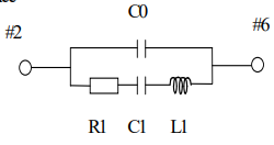 1 port resonators are intended for use where the circuit they are in operates with a low phase shift across the resonator. This is the most common variety.
2 Port Resonators
Here the equivalent circuit: 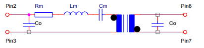 The addition of the transformer in this model adds a 180° phase shift. This type of resonator is intended for oscillator circuits where there is close to an inversion between input and output. It is not an exact inversion as like the 1 port resonator C0 adds an additional phase shift.
Minimum Required specifications
This is the minimum set of requirements we would like from a customer to specify a SAW resonator. Often if designing for a specific chip you will find guide values for these parameters in the data sheet for the chip or associated application notes.
Frequency
Usually self evident and is set by the application. SAW resonators are always specified at their series resonance. This is in contrast with crystals where a parallel resonance with an externally applied load capacitance is most common. The series resonance is defined by the point of maximum real part of the measured admittance. This method eliminates the effect of C0 in the measurement. It is tempting to measure the resonator in series using a VNA and assume the point of lowest insertion loss is the series resonance. This will produce slightly incorrect results.
Case Size
Leaded types have largely been phased out so are now hard to obtain and not recommended for new designs. The most common case size is 3.0 x 3.0 mm.
Tolerance
This is the allowed manufacturing variation from the nominal frequency measured at 25°C. Often this is quoted in kHz rather than ppm. Care should be taken over the units being used.
Stability
This is the amount the resonant frequency varies from that measured at 25°C. SAW resonators are based on XT cut quartz so have the same parabolic temperature characteristic as tuning fork crystals.
Operating Temperature Range
The temperature range for which the stability is specified. If no other information is given this will be taken as the storage temperature range.
Insertion Loss
This is a proxy for defining the motional resistance R1.
Optional Specifications
The above will give a crystal supplier the basics to select a suitable crystal for an application where the specifications are not tight for instance USB 1 and 2 or a microcontroller where the timing is not critical. Where more accurate timing is required or less usual operating conditions apply then the parameters below should be considered.
Input Power Level
This is the power dissipated in the crystal while working in its oscillator circuit. When characterising a crystal a supplier will use one drive level to measure most of the parameters. This level will be indicated in the data sheet as the typical drive level. For AT cut crystal frequency and motional resistance can vary with high drive level. The onset of this variation with rising drive level is given by the maximum drive level in the data sheet. Tuning fork crystals can be damaged by excessive drive so the maximum given in the data sheet should not be exceeded.
Q Factor
Calculated from R1 and C1. This is a useful parameter to define if phase noise performance of the oscillator is critical.
Storage Temperature Range
This is as the name suggests.
Motional Capacitance (C1) and C0
If you are tuning the resonator by varying the operating phase shift through the resonator, then it becomes important to specify these parameters. These set the tuning range that will be achieved. Please consult us for typical values for a given case size and frequency.
Calculating Overall Frequency Error.
This industry standard method is to simply add Tolerance, Stability, error due to and variation in the phase shift of the rest of the oscillator circuit. A more scientifically correct approach is to use a statistical method. The above error sources are uncorrelated, so the simple addition gives a pessimistic view.